- 您现在的位置:买卖IC网 > Sheet目录3832 > AT87C54X2-3CSUL (Atmel)IC 8051 MCU 16K EPROM 40DIP
15
4431E–8051–04/06
AT/TS8xC54/8X2
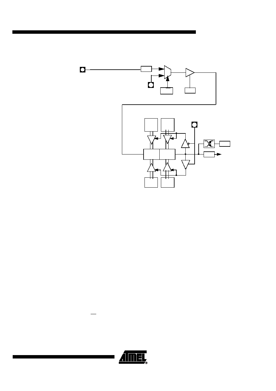
Figure 8-1.
Auto-Reload Mode Up/Down Counter (DCEN = 1)
8.1.1
Programmable Clock-Output
In the clock-out mode, timer 2 operates as a 50%-duty-cycle, programmable clock generator
(See Figure 8-2) . The input clock increments TL2 at frequency F
OSC/2. The timer repeatedly
counts to overflow from a loaded value. At overflow, the contents of RCAP2H and RCAP2L reg-
isters are loaded into TH2 and TL2. In this mode, timer 2 overflows do not generate interrupts.
The formula gives the clock-out frequency as a function of the system oscillator frequency and
the value in the RCAP2H and RCAP2L registers :
For a 16 MHz system clock, timer 2 has a programmable frequency range of 61 Hz
(F
OSC/2
16) to 4 MHz (F
OSC/4). The generated clock signal is brought out to T2 pin (P1.0).
Timer 2 is programmed for the clock-out mode as follows:
Set T2OE bit in T2MOD register.
Clear C/T2 bit in T2CON register.
Determine the 16-bit reload value from the formula and enter it in RCAP2H/RCAP2L
registers.
(DOWN COUNTING RELOAD VALUE)
C/T2
TF2
TR2
T2
EXF2
TH2
(8-bit)
TL2
(8-bit)
RCAP2H
(8-bit)
RCAP2L
(8-bit)
FFh
(8-bit)
FFh
(8-bit)
T OG-
(UP COUNTING RELOAD VALUE)
TIMER 2
INTERRUPT
XTAL1
:12
F
OSC
FXTAL
0
1
T2CONreg
T2EX:
if DCEN=1, 1=UP
if DCEN=1, 0=DOWN
(:6 in X2 mode)
Clock OutFrequency
–
Fosc
4
65536
RCAP2H
–
RCAP2L
()
×
-----------------------------------------------------------------------------------------
=
发布紧急采购,3分钟左右您将得到回复。
相关PDF资料
AT87C52X2-SLSUM
IC 8051 MCU 8K OTP 40MHZ 44PLCC
PIC16LF76-I/SP
IC PIC MCU FLASH 8KX14 28DIP
PIC18LF2431-I/SO
IC MCU FLASH 8KX16 28SOIC
AT87C52X2-SLSUL
IC 8051 MCU 8K OTP 30MHZ 44PLCC
PIC32MX420F032H-40V/PT
IC MCU 32BIT 32KB FLASH 64TQFP
PIC32MX320F064H-40V/PT
IC MCU 32BIT 64KB FLASH 64TQFP
DSPIC33FJ64GP306A-I/PT
IC DSPIC MCU/DSP 64K 64-TQFP
AT87C52X2-RLTUM
IC 8051 MCU 8K OTP 40MHZ 44VQFP
相关代理商/技术参数
AT87C54X2-3CSUM
功能描述:8位微控制器 -MCU MICRO OTP RB/16K 40MHZ 5V C RoHS:否 制造商:Silicon Labs 核心:8051 处理器系列:C8051F39x 数据总线宽度:8 bit 最大时钟频率:50 MHz 程序存储器大小:16 KB 数据 RAM 大小:1 KB 片上 ADC:Yes 工作电源电压:1.8 V to 3.6 V 工作温度范围:- 40 C to + 105 C 封装 / 箱体:QFN-20 安装风格:SMD/SMT
AT87C54X2-3CSUV
制造商:ATMEL 制造商全称:ATMEL Corporation 功能描述:8-bit CMOS Microcontroller 16/32 Kbytes ROM/OTP
AT87C54X2-RLTUL
功能描述:8位微控制器 -MCU OTP C54/16K 40MHZ 3V COM TEMP RoHS:否 制造商:Silicon Labs 核心:8051 处理器系列:C8051F39x 数据总线宽度:8 bit 最大时钟频率:50 MHz 程序存储器大小:16 KB 数据 RAM 大小:1 KB 片上 ADC:Yes 工作电源电压:1.8 V to 3.6 V 工作温度范围:- 40 C to + 105 C 封装 / 箱体:QFN-20 安装风格:SMD/SMT
AT87C54X2-RLTUM
功能描述:8位微控制器 -MCU OTP C54B/16K 40MHZ 5V COM TEMP RoHS:否 制造商:Silicon Labs 核心:8051 处理器系列:C8051F39x 数据总线宽度:8 bit 最大时钟频率:50 MHz 程序存储器大小:16 KB 数据 RAM 大小:1 KB 片上 ADC:Yes 工作电源电压:1.8 V to 3.6 V 工作温度范围:- 40 C to + 105 C 封装 / 箱体:QFN-20 安装风格:SMD/SMT
AT87C54X2-RLTUV
制造商:ATMEL 制造商全称:ATMEL Corporation 功能描述:8-bit CMOS Microcontroller 16/32 Kbytes ROM/OTP
AT87C54X2-SLRUM
功能描述:8位微控制器 -MCU 16K 40MHz RoHS:否 制造商:Silicon Labs 核心:8051 处理器系列:C8051F39x 数据总线宽度:8 bit 最大时钟频率:50 MHz 程序存储器大小:16 KB 数据 RAM 大小:1 KB 片上 ADC:Yes 工作电源电压:1.8 V to 3.6 V 工作温度范围:- 40 C to + 105 C 封装 / 箱体:QFN-20 安装风格:SMD/SMT
AT87C54X2-SLSUL
功能描述:8位微控制器 -MCU OTP C54/16K 40MHZ 3V COM TEMP RoHS:否 制造商:Silicon Labs 核心:8051 处理器系列:C8051F39x 数据总线宽度:8 bit 最大时钟频率:50 MHz 程序存储器大小:16 KB 数据 RAM 大小:1 KB 片上 ADC:Yes 工作电源电压:1.8 V to 3.6 V 工作温度范围:- 40 C to + 105 C 封装 / 箱体:QFN-20 安装风格:SMD/SMT
AT87C54X2-SLSUM
功能描述:8位微控制器 -MCU OTP C54/16K 40MHZ 5V IND TEMP RoHS:否 制造商:Silicon Labs 核心:8051 处理器系列:C8051F39x 数据总线宽度:8 bit 最大时钟频率:50 MHz 程序存储器大小:16 KB 数据 RAM 大小:1 KB 片上 ADC:Yes 工作电源电压:1.8 V to 3.6 V 工作温度范围:- 40 C to + 105 C 封装 / 箱体:QFN-20 安装风格:SMD/SMT